Installation Instructions for Stainless Steel Flanges abstract
Installation Instructions for Stainless Steel Flanges are documented procedures specifying the preparation, alignment, and bolted connection tightening sequence/torque values required to assemble stainless steel flanged joints correctly, ensuring a permanent leak-proof seal according to applicable standards.
Key elements covered precisely:
- Defined as: Documented procedures
- Scope: For Stainless Steel Flanged Joints
- Content Specifies:
- Preparation (surfaces)
- Alignment
- Bolted connection tightening (sequence & torque values)
- Purpose: Correct assembly ensuring a permanent leak-proof seal
- Basis: According to applicable standards (e.g., ASME B16.5, EN 1092-1)
Introduction to Stainless Steel Flanges
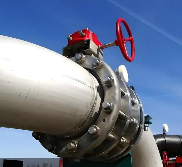
Stainless steel flanges are essential components in piping systems, offering superior corrosion resistance and structural integrity. Their installation requires careful attention to detail to ensure leak-proof connections and long-term performance. This guide covers comprehensive installation procedures for all major flange types including stainless steel slip on flange, stainless steel weld neck flange, stainless steel blind flange, stainless steel lap joint flange, stainless steel socket weld flange, and stainless steel thread flange.
Pre-Installation Preparation-Installation Instructions for Stainless Steel Flanges
Surface Cleaning
- Remove all contaminants from pipe ends and flange faces using appropriate cleaning solvents
- Verify surface smoothness (Ra ≤ 3.2 μm for standard applications)
- Check for scratches or imperfections exceeding 0.1mm depth
Equipment Verification
| Tool/Equipment | Specification Requirement |
|---|---|
| Torque Wrench | ±5% accuracy |
| Alignment Pins | Hardness ≥ HRC 40 |
| Gasket Cutter | Tolerance ±0.5mm |
Step-by-Step Installation Procedure-Installation Instructions for Stainless Steel Flanges
1. Pipe End Preparation Installation Instructions for Stainless Steel Flanges
For stainless steel slip on flange and stainless steel weld neck flange:
- Perform 90° flanging with controlled parameters:
- Flange angle tolerance: 89°-91°
- Flange thickness reduction: ≤10% of original wall thickness
- Surface roughness after machining: ≤6.3μm
2. Flange Alignment
Critical alignment specifications:
- Parallelism deviation: ≤0.2mm per 100mm diameter
- Concentricity tolerance: ≤1% of pipe OD
- Gap uniformity: ±0.5mm around circumference
3. Gasket Installation
Recommended compression factors:
| Gasket Type | Compression % | Stress (MPa) |
|---|---|---|
| Spiral Wound | 25-30 | 40-70 |
| Flat Graphite | 15-20 | 20-40 |
| Metal Jacketed | 30-35 | 60-100 |
4. Bolt Tightening Sequence
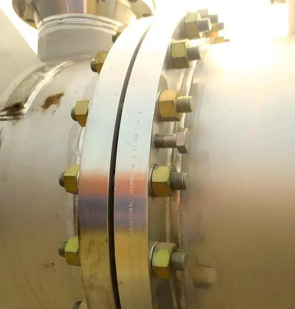
Follow cross-pattern tightening in at least 4 stages:
- Initial snugging at 30% final torque
- 60% torque application
- 90% torque verification
- Final 100% torque in sequence
Torque values for common sizes:
| Bolt Size (mm) | Torque (Nm) | Passes Required |
|---|---|---|
| M16 | 110-130 | 3-4 |
| M20 | 180-210 | 4-5 |
| M24 | 280-320 | 5-6 |
Specialized Installation Techniques-Installation Instructions for Stainless Steel Flanges
For Stainless Steel Blind Flange
- Apply thread sealant meeting ASTM D5363 standards
- Use calibrated tensioning devices for bolts >1″
- Maintain uniform loading within ±10% variation
For Stainless Steel Lap Joint Flange
- Stub end alignment must satisfy:
- Axial offset ≤0.5mm
- Angular misalignment ≤0.5°
- Backing ring clearance: 1-2mm
For Stainless Steel Socket Weld Flange
Critical weld parameters:
| Pipe Size (NPS) | Root Gap (mm) | Number of Passes |
|---|---|---|
| ≤2 | 1.5-2.0 | 2 |
| 2-6 | 2.0-2.5 | 3 |
| >6 | 2.5-3.0 | 4 |
For Stainless Steel Thread Flange
- Apply thread compound containing >85% metallic solids
- Make-up torque requirements:
Pipe Size Torque (ft-lbs) Turns Past Hand-Tight 1/2″ 40-50 1.5-2 1″ 80-100 2-2.5 2″ 160-180 2.5-3
Quality Control Measures-Installation Instructions for Stainless Steel Flanges
Pressure Testing Protocol
- Hydrostatic test: 1.5x design pressure for 30 minutes
- Pneumatic test: 1.1x design pressure with bubble solution inspection
- Allowable leakage: ≤3 bubbles/minute per NPS inch
Post-Installation Inspection
Checklist items:
- Bolt stress verification using ultrasonic measurement
- Flange face flatness (≤0.05mm across any diameter)
- Gasket compression uniformity (±15% variation)
Maintenance Considerations
- Retorquing schedule: After 24 hours of operation and at 500-hour intervals
- Corrosion monitoring: Conduct annual ultrasonic thickness testing
- Gasket replacement criteria: When compression set exceeds 20%
This comprehensive guide ensures proper installation of all stainless steel flange types while meeting international standards including ASME B16.5, EN 1092-1, and ISO 7005-1. The procedures account for material properties of 304/304L and 316/316L stainless steel grades commonly used in flange manufacturing.
Summary: Installation Instructions for Stainless Steel Flanges
The comprehensive guide details proper installation procedures for six types of stainless steel flanges (slip-on, weld neck, blind, lap joint, socket weld, and threaded). Key steps include thorough surface preparation, precise alignment (≤0.2mm/100mm tolerance), controlled gasket compression (15-35% depending on type), and systematic bolt tightening in multiple passes (typically 3-6 stages). Specialized techniques are provided for each flange variety, including welding parameters for socket weld flanges (1.5-3.0mm root gaps) and make-up torque specifications for threaded flanges (40-180 ft-lbs).
The article emphasizes quality control through hydrostatic testing (1.5x design pressure) and post-installation inspections checking bolt stress, flatness (≤0.05mm), and gasket compression uniformity (±15%). Maintenance protocols include 24-hour retorquing and annual corrosion monitoring, ensuring long-term performance of these corrosion-resistant components in demanding industrial applications.


